
I’ve seen a few people lately make boxes for all their battery chargers so they can just plug one them in and then have all their chargers set up. However, most of them relied on using a number of the different power supplies and sometimes running a power strip, which take up a load of weight and space. I’ve decided to make one but cut it down to be lighter weight and to also have the option of plugging in to a battery or car DC connection in case of being away from mains.
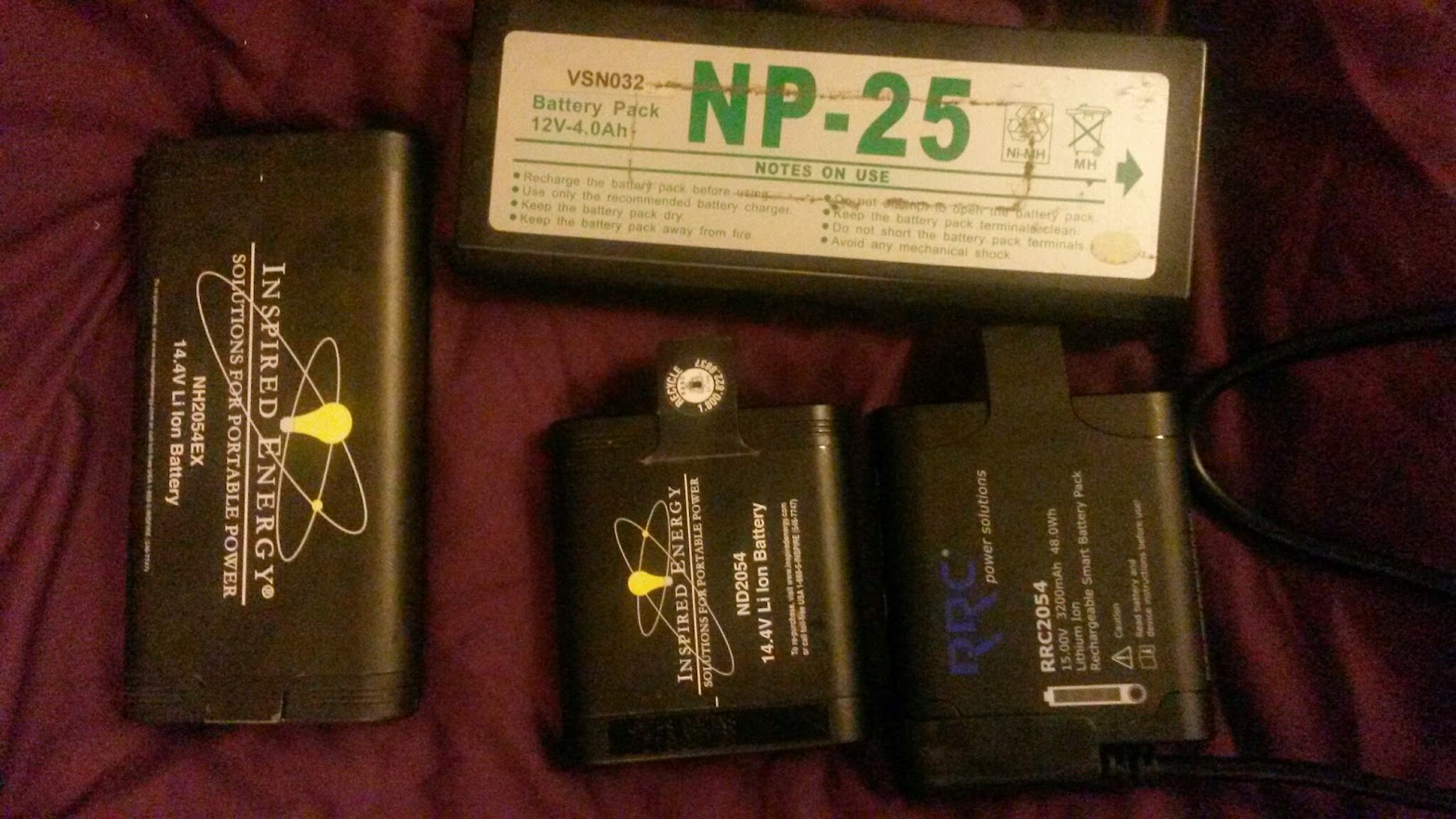
So, first of all I needed to figure out what to was going in and what was required to power it. I thought about 20 AA batteries is about the maximum I’d go through in a day (I try not to use any other kinds) . I also use 2054 style SMbus batteries- both the chargers for these are small but require external power supplies, and they take a 24V input. I also use USB to recharge my Timecode Systems boxes (and some USB batteries, and *everyone* wants a phone charger).
So (according to the manuals/existing power supplies)
2x AA chargers on 12V (1.5A each)
2x SMbus on 24V (2.5A each 5A total)
USB on 5V 2A
and I need something to power all that…
So, basic electricity time:
Power = Voltage x Current
Components will only work within a specific voltage range (otherwise they don’t work or break) and will draw up to a certain current. So the voltage is the ‘level’ of electricity and the current is the amount it uses.
So 1A of current at 12V = 12W of power
12W divided by 24V = 0.5A of current
so, to provide the same amount of current at twice the voltage requires twice as much power.
So, the SMbus chargers need 100W, AA chargers need 36W and USB needs 10W. In all that would need a 150W PSU to run everything at once at max power.
I actually ended up getting 2 under-specced 90W PSU as they were smaller and lighter, had variable voltage, USB built in and a display. However it may mean it’ll top out (7.5A) if everything’s on at once, which may mean some things won’t charge as quickly. It’ll also turn off if it gets too hot. The second can be used too if I need additinal power or even to power my cart
The 5V line is taken care of but what about either the 24V or 12V? Although it’s usually more straightforward to reduce voltage, I decided to run the PSU at 12V and get a 12V to 24V step up converter which will handle 120W. This way, it gives the option of swapping the PSU out for a 12V battery. I made all the linking cables up with 4pin XLR connectors, which is fairly standard for DC power distribution, and means the various components can still be used separately.
Here’s all the individual components connected together:

Ends were cut off most of the cables to replace with 4 Pin XLR connectors and the 24V output was soldered directly on. I also used right angled DC jacks to save space and avoid pressure on the cables when in the box.
For the box I used one of the newer Orca accessory bags made of moulded EVA plastic. It’s considerably lighter than a Peli case, yet still seems rather durable:
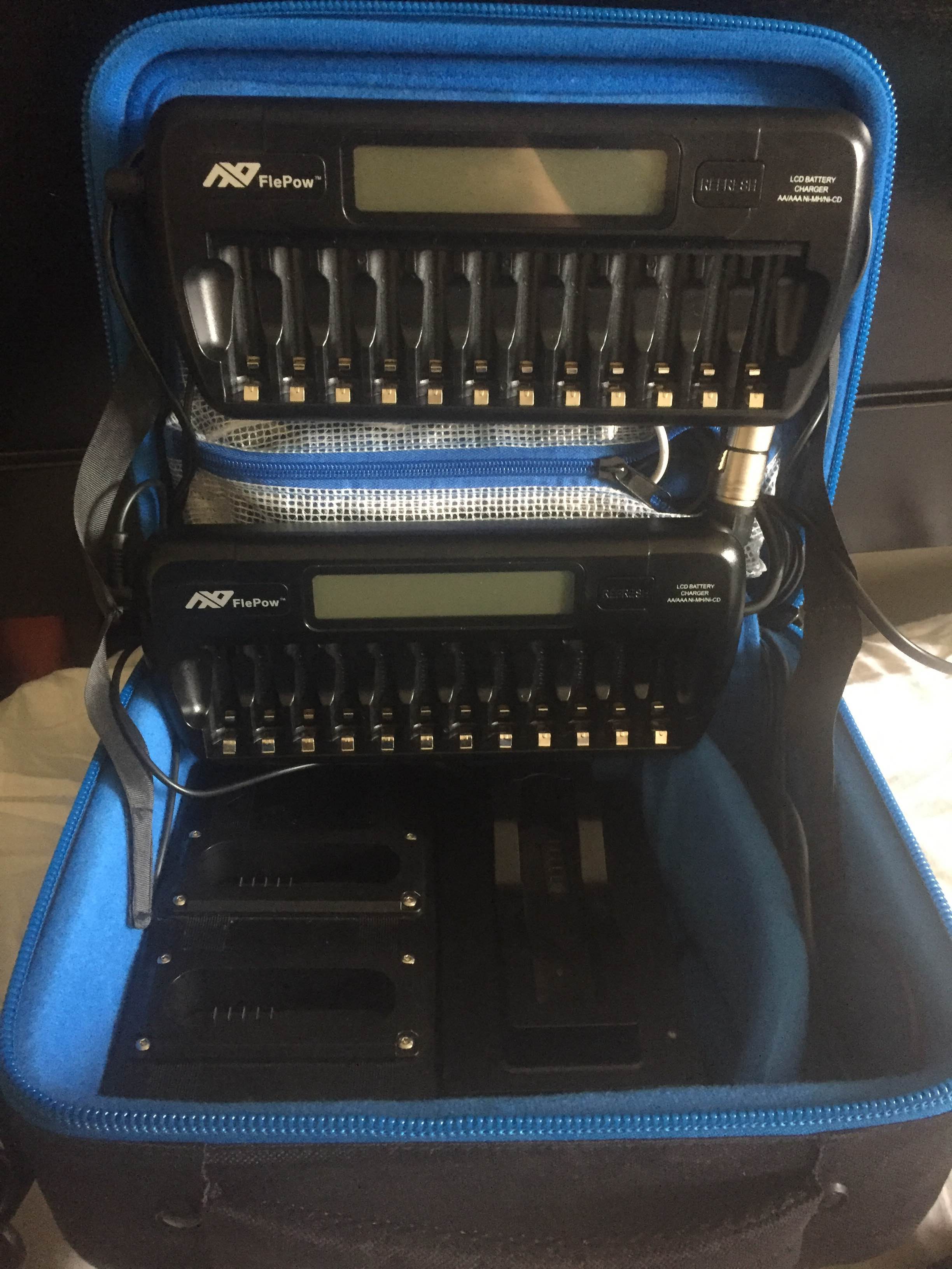
The AA chargers are velcroed to the pockets which contain the PSU, step up converter and USB hub. It’s a bit top heavy, so I may remove the support straps in the case to let the lid fall back as it falls over if not leaning against something. There’s a channel under the material on the hinge which makes a neat place to run cables too.
The USB cables run to the section to the bottom right, so whatever’s being charged can go there, and the plug can fit there when being transported